ILum is an interactive display consisting of LED strips installed on individual rails to allow the user to shape it as they wish.
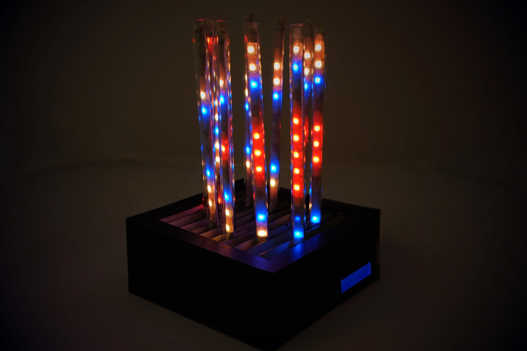
This tabletop device synchronizes with music to create light patterns.
This tabletop device synchronizes with music to create light patterns.

Music synchronized
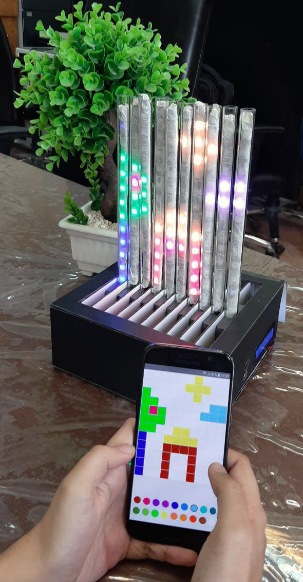
A web-based application can be used on your phone or PC to paint on the display.
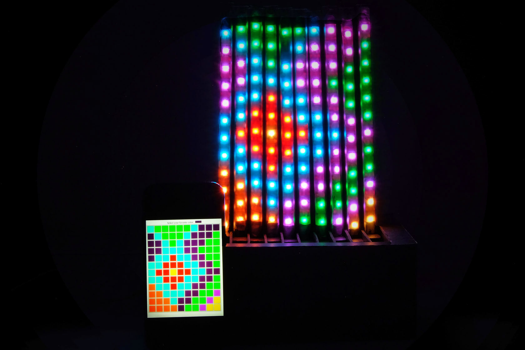
Paint with phone
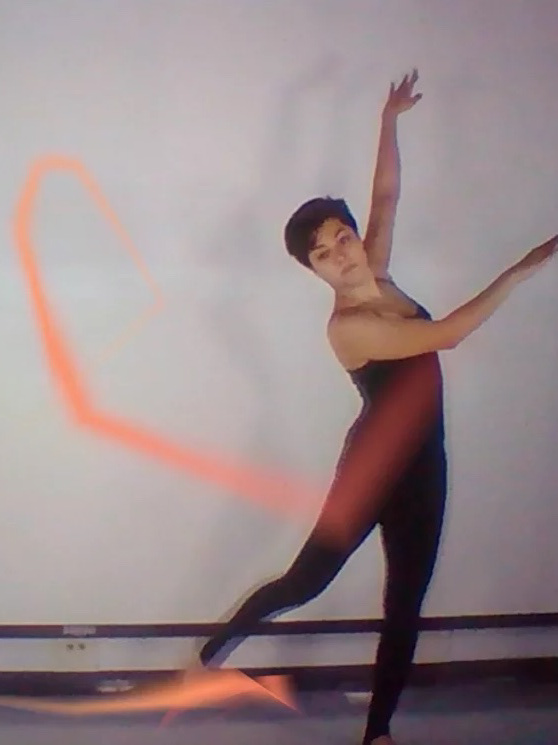
When you are not feeling playful, you can use ILum as a desk clock or night lamp
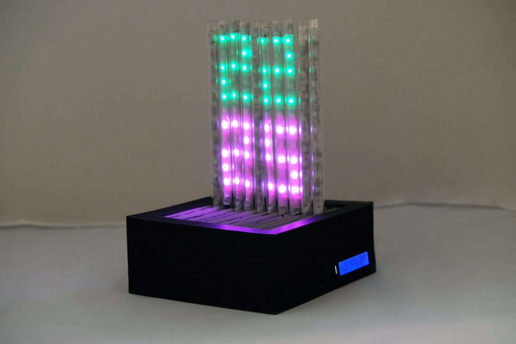
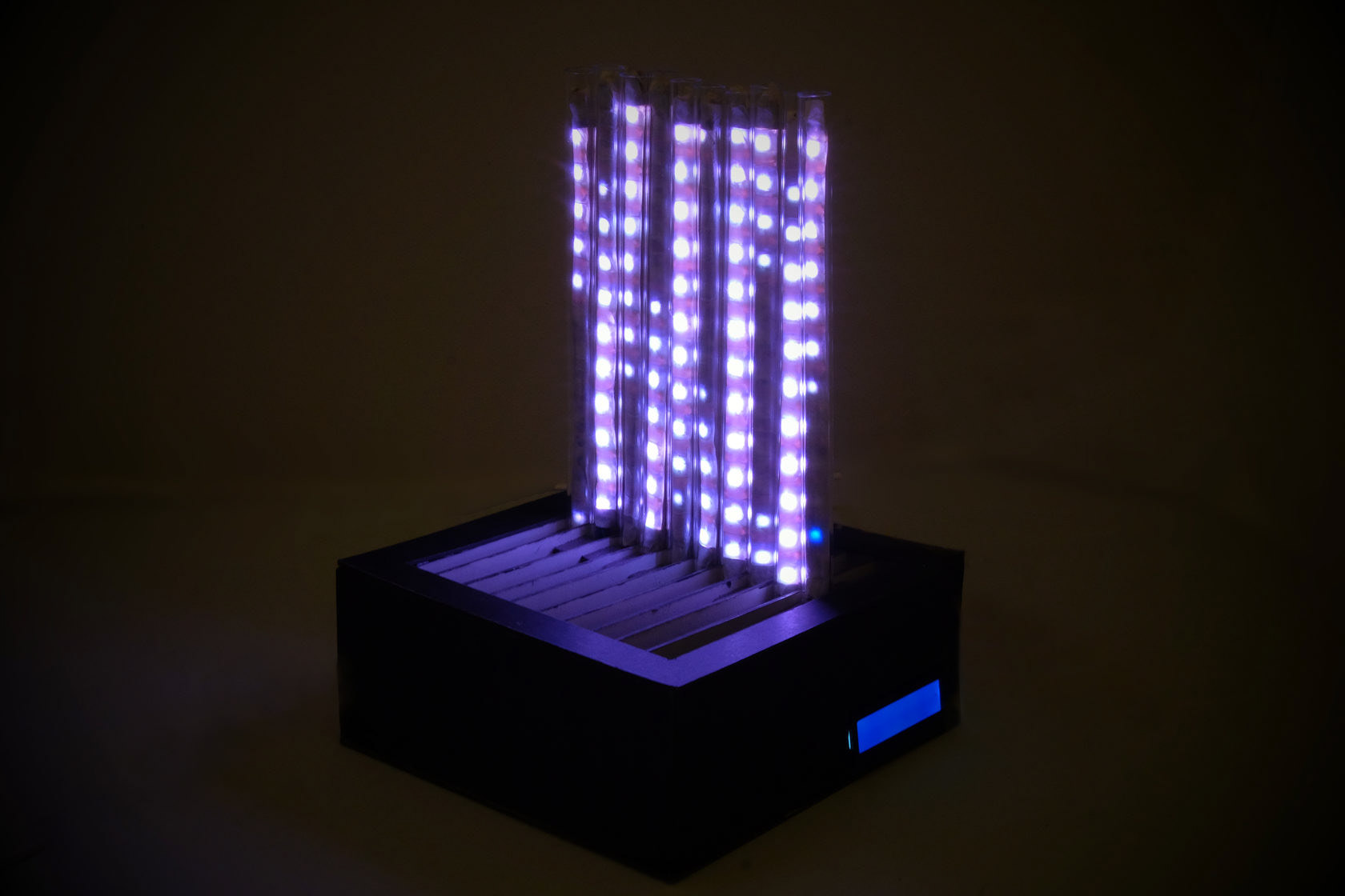
A distinguishing feature of ILum is that each LED-strip can be moved in its rail to form various physical appearances.

An LCD display is located at the side to show its status. The device mode is controlled by a button.
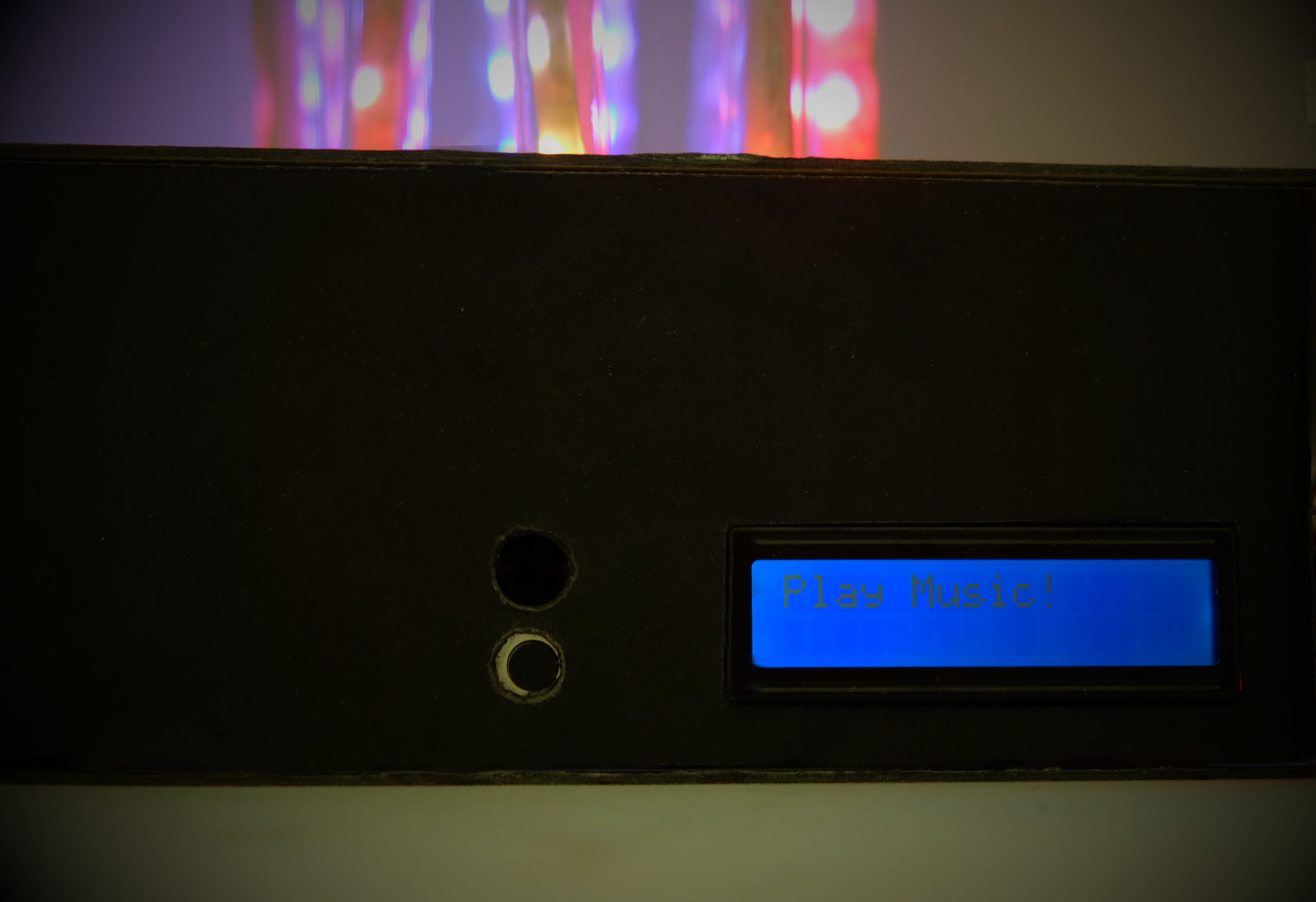
LCD, button, and microphone on the side
Development Process
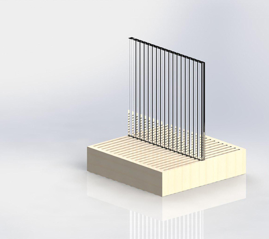
Step 1. Simulation
We started off by listing our main features which included flexibility of physical appearance, multiple daily purposes, and a clean design. After designing the appearance and deciding on the features, we made the following 3D model.

For the technical platform, we decided to use Arduino as we didn't have any complex computations.
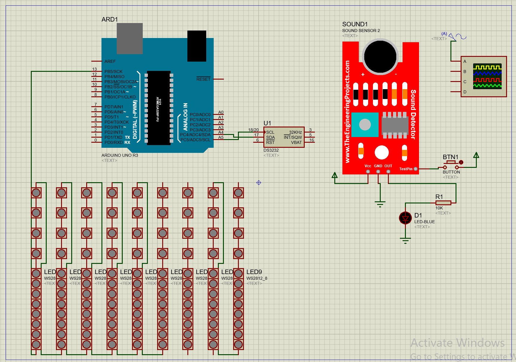
We then developed and simulated each model (the clock, music reactivity) on the Proteus Design Suite software.
This step allowed us to test our codes without having made the physical device. It also gave us an overall idea of the final product.
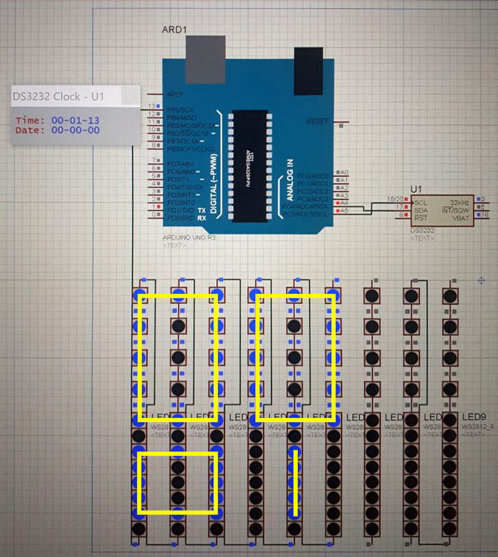
We then developed and simulated each model (the clock, music reactivity) on the Proteus Design Suite software.
This step allowed us to test our codes without having made the physical device. It also gave us an overall idea of the final product.

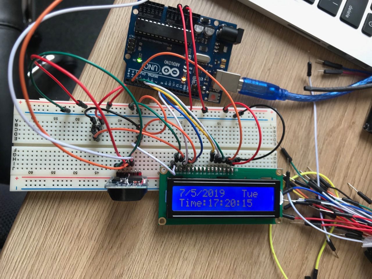
Step 2. Hardware Test
After writing the codes and testing the software, it was time to start building the device. We tested each module individually, then made the screen to test our codes.
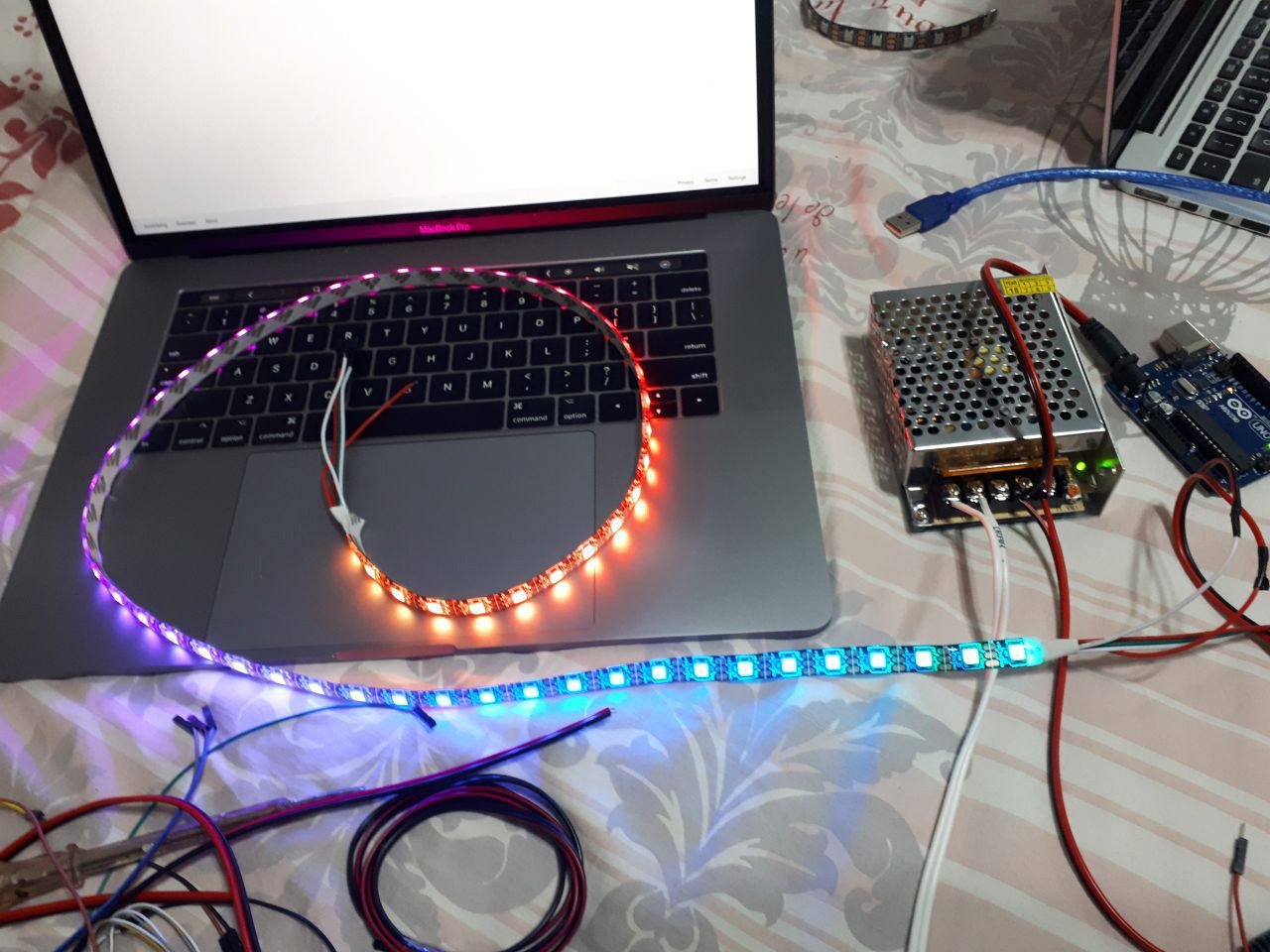
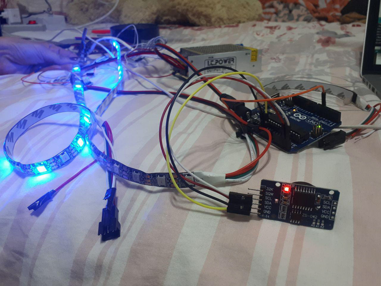

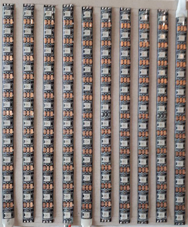
After checking each module and mode, we made the display by cutting and aligning LED strips on a surface and wiring them.
The last part of the project was connecting it to another device via the internet and being able to draw on it using the mobile application or web.
For this purpose, we wrote an android application as well as a web page. When you put the device on paint mode, the wifi module is listening on a constant local IP and awaiting commands.
Below you can see the first demo of painting on the screen with the android app being run on a PC.
Step 3. Combination
As the features were working perfectly, we could combine them together. For this purpose, we added a button to change the state of the device.
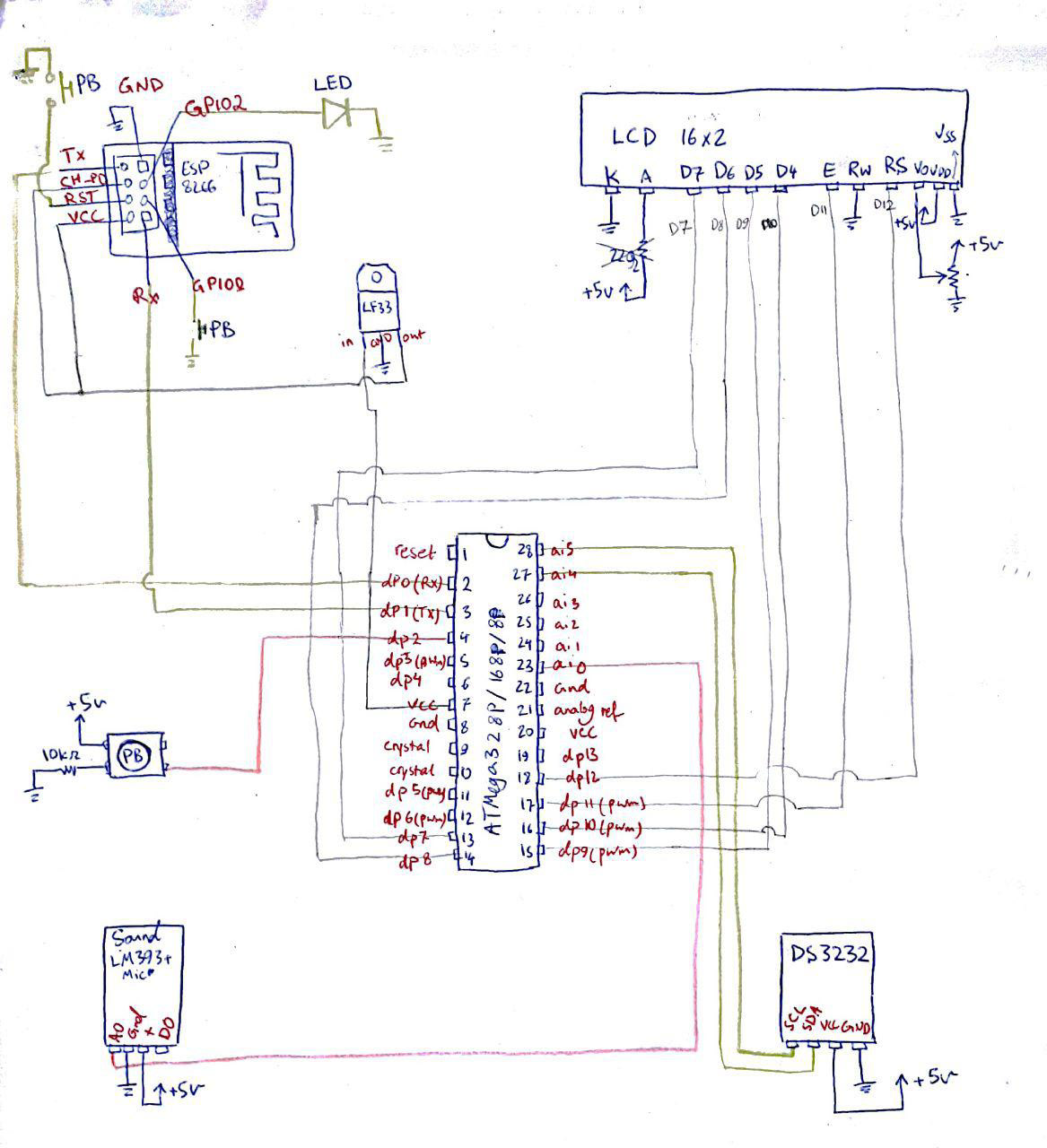
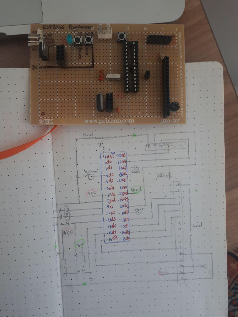
For the final product, we designed the following data sheet which includes:
ATMega328p, serving as the microprocessor,
Button, to change device mode,
LCD, to show the mode and extra information,
DS3232 module for showing time,
ESP8266 module for wifi connection.
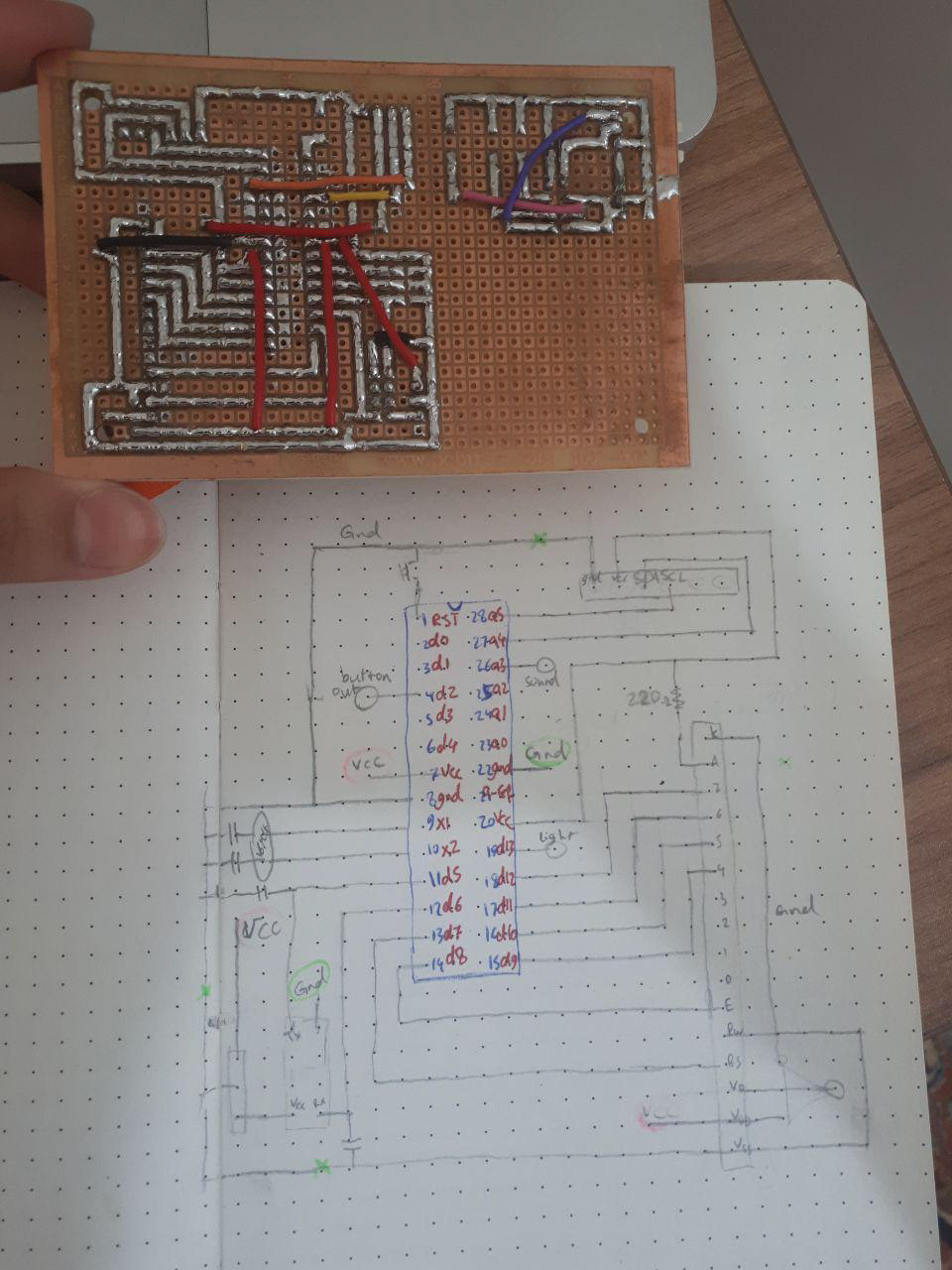
The board was then soldered and embedded in the box underneath the device.
For the physical appearance, glass tubes were used to hold the LED strips. Each tube was fixated on its stand, allowing it to move and preventing it from collapsing.
This project is open-sourced and can be found on my Github.